Services
We supply, automate, and integrate portable solutions for industrial metrology.
Automation & Integration
Automate recurring measurement sequences and metrology-supported assembly processes.
VMT’s sophisticated solutions open new possibilities by optimising processes and reducing both costs and risk of human error.
This can involve the measurement of serial components, regularly scheduled periodic inspections or complex parts with demanding geometries and tight tolerances. Nominal-actual comparisons as well as plausibility and completeness checks further develop quality assurance into an integral part of your production processes.
Whether operator-supporting, partially integrated systems or operator-guiding, fully integrated solutions: With us, you receive all services from a single source – from consulting and conception (including benchmark-based hardware and software configuration) through to on-site implementation and validation. The training of subsequent users in ongoing production as well as the unique Support+ round off our complete package.
Automation with VMT: Get more value out of your measurement data
Precision, permanently available
The data acquired by measurement systems is an asset for your manufacturing processes, opening a wide range of possibilities. VMT enables you to fully realise the potential of quality industrial metrology: Where tight tolerances are important, VMT’s automation solutions create the prerequisites for traceable, repeatable, and thus fully production-capable metrology systems. At the same time, they are designed to be so user-friendly that they can be operated by production workers on the factory floor at any time – without the need for a lengthy training.
One solution, many benefits
Operational improvements that metrology automation brings are far-reaching. With professional project and change management, the standardisation of processes, clever features such as XML MAA (Measurement Assisted Assembly), native CAD support and project-related maintenance and support options, smooth, trouble-free production becomes a reality. Intelligently networked and integrated via manufacturer-independent interfaces, VMT’s solutions pave your way to Industry 4.0 though countless new opportunities and perspectives. Ask us for a customised offer for your individual process!
Operator supported automation
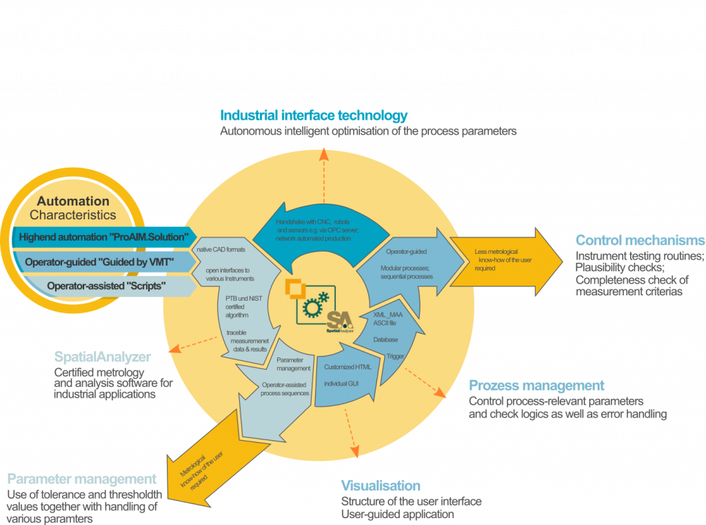
Designed for users with metrology expertise, this solution is the simplest type of metrology automation and is therefore the quickest and easiest way to increase manufacturing capacity or production rates. During the measurement process, the operator receives support through the SpatialAnalyzer user interface. Automating and thus standardising this process reduces the risk of human error, while practice-oriented features increase convenience.
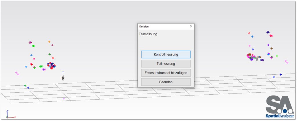
As a result, not only process interruptions, and restarts are possible at any time: Measurement plans (MPs) are also stored in script form in SpatialAnalyzer, making them more versatile and flexible than ordinary macros. Using metrology automation, you can also create generally valid processes that continue to run reliably even when various parameters are changed, user queries are made, or instrument interfaces are modified. And with automatic reporting, you have an accurate overview at all times.
Operator-guided automation
Operator-guided automation extends the possibilities of operator-supported automation using powerful modules. These offer you an additional benefit in terms of functions and user-friendliness:
Self-explanatory operator guidance offers customisable interfaces using HTML, configurable input conditions, and clear visual and acoustic communication. Guided metrology processes remove any complication from controlling the automation. As a result, metrological expertise is not a prerequisite for operation.
Additional process reliability is provided by a wide range of checks, including measured values for RMS or test routines for instruments, such as a drift check, completeness of measurement criteria, or plausibility. Parameter management, such as those for tolerances, is conveniently carried out via an ASCII file in XML format.
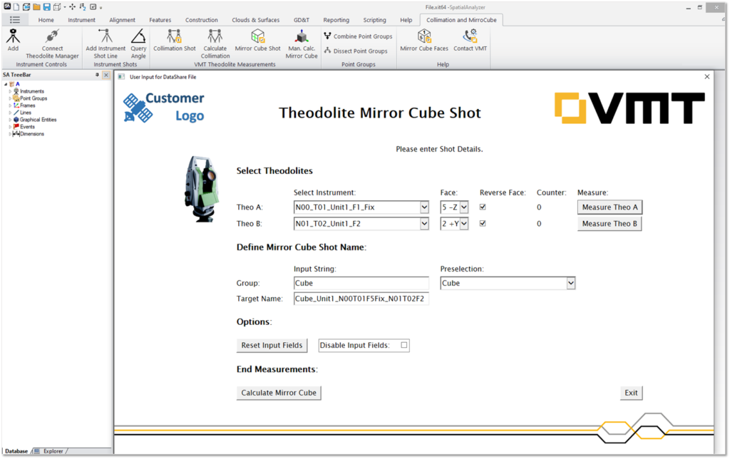
ProAIM.Solution: Automation for the highest demands
| VMT’s high-end ProAIM.Solution offers a wide range of functions, control options and industrial interfaces for maximum process security. Integrating structures for user rights and databases makes it easier to manage relevant component data, manufacturing tolerances, and parameters. Using sophisticated data management (SPC), permanently retrievable process status, generation of protocols for inspected objects and meaningful reporting, no relevant information is missed. |
To optimise user experience, we tailor the interface (HMI) to your manufacturing process; this can be divided into individual modules for further flexibility. Due to the deep communication between ProAIM.Solution and SpatialAnalyzer SDK, integrating external processes for plant and machine control is easy. CNC systems(e.g. Siemens Sinumerik) or robots are controlled using OPC servers.
ProAIM.Solution is available as a standalone metrology platform and as a service client. Learn more here.
Automation solutions with SpatialAnalyzer
VMT implements automations individually and customised to the metrology process with the metrology software SpatialAnalyzer using simple measurement scripts or fully autonomous complete solutions. Have a look to see how this can be used in practice:
Integration of Metrology: From consulting to production interface
Added value made easy: VMT offers comprehensive, all-in-one solutions
Experience the full range of possibilities inherent in industrial measurement technology and its integration into individual applications. Precise control and monitoring of manufacturing processes is possible, as well as the final QA measurement of manufactured components.
To ensure that the best possible solution, VMT assists with the entire path to implementation, including manufacturer-independent consulting regarding the appropriate measurement technology, the performing of test measurements, and creation of detailed benchmarks. The result is a metrology system able to be worked with immediately, including accessories, such as stands, SMRs, target holders and metrology software.
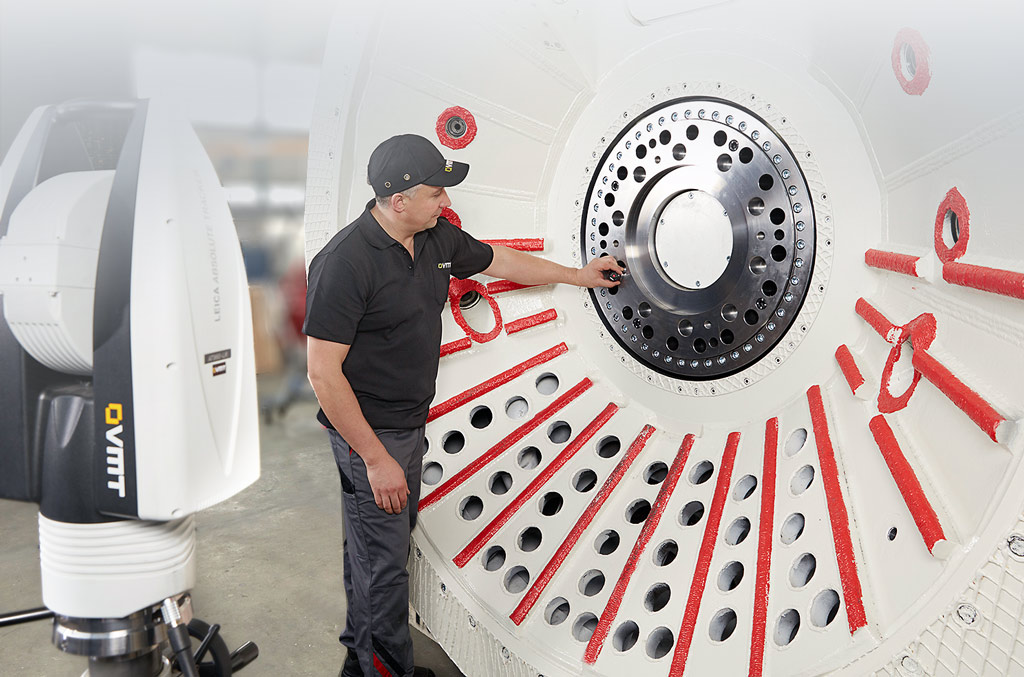
One application example is VMT’s LIS system, designed for segment and mould measurements in tunnel construction. Learn more about it here:
One step ahead: Automation of integrated measurement technology
Benefit from features and efficiency improvements in daily production by integrating measurement technologies with user-guided or user-supported automation.
The available technical options can be as diverse as the required measurement tasks. Measurements are started from a trigger signal, controlled via I/O, or the self-tracking reflectors for 3D and 6DoF measurements, scanning and tactile measurements.
Hardware components can be further integrated by means of metrological support. For example, machines or robots can be moved to precise positions in relation to your object using Move-Measure-Correct. to increase the manufacturing accuracy in production.

Christian Lüdiger
Team Leader IMS
Software & Integration
Phone
Interested in automation?
We’re delighted to discuss possible solutions to your challenges with you.
Portable 3D measurement service
Rely on our specialists and state-of-the-art measurement technology.
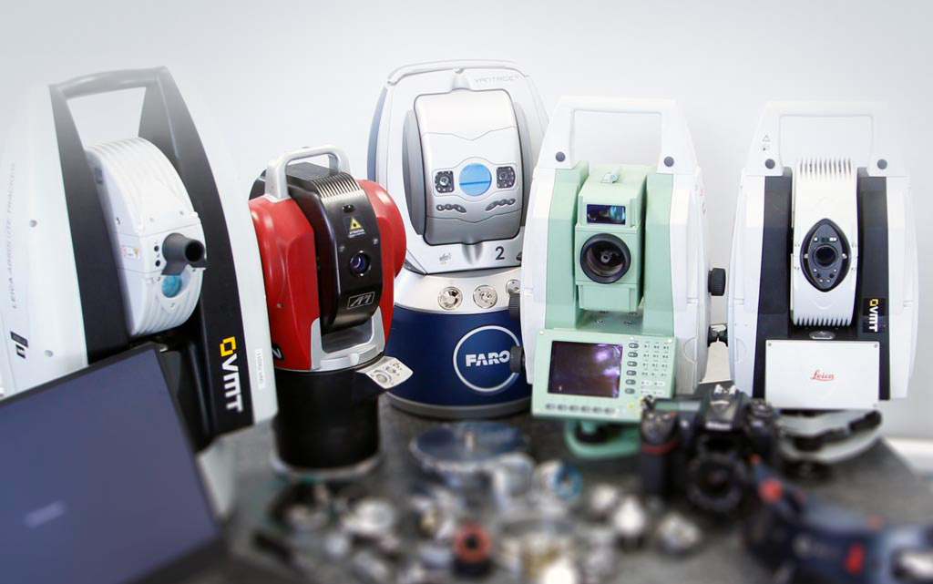
Every measurement task requires a specific approach. That is why we perform non-contact and tactile, static, and dynamic, as well as large and small volume measurements using laser trackers, scanners, photogrammetry and more, either on-site or in the VMT metrology laboratory.
Every measurement task requires a specific approach. That is why we perform non-contact and tactile, static, and dynamic, as well as large and small volume measurements using laser trackers, scanners, photogrammetry and more, either on-site or in the VMT metrology laboratory.
The latest technology in portable 3D metrology equipment and cross-industry know-how of VMT’s engineers delivers the best possible results, including reliable data with significant analyses, reports for the measurement of components, machines, plants, and for smooth production processes.
As nuances are what determine efficiency or rejects, create certainty and reliability with VMT’s certified and calibrated measuring systems when maximum accuracy is required in production.
VMT’s service offerings address all relevant phases and areas of manufacturing processes, including measuring, and evaluating the quality of serial components, robots, or entire systems, as well as performing first-article and GD&T inspections and support adjustments. VMT’s range of offerings also includes measurement uncertainty analysis, simple geometric measurement with comparison to CAD data and metrological support of assembly processes. VMT’s services also include the tracking of dynamic movements and deformations as well as the inspection of production lines and instruments, including the preparation of inspection certificates.
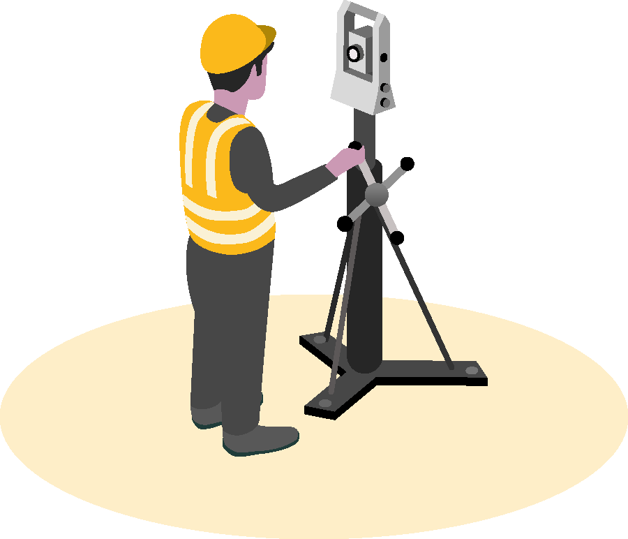
Adjustment and jig measurement
Ensure that full functionality is permanently maintained by setting up precise individual jigs as well as complex assemblies of production cells and production lines, whether during initial installation, adjustment after longer use or within the scope of periodic inspection intervals.
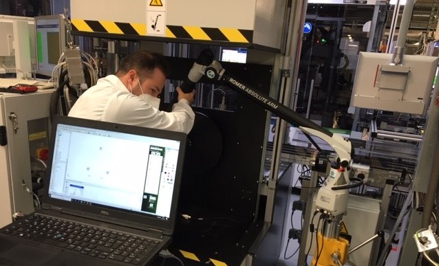
- Positions of all components, fittings, brackets, and so on are measured with laser trackers or PCMMs and compared to the nominal CAD model.
- Actual deviations are logged both graphically and in tabular form. This allows an immediate correction of the test item on-site with fitters and project managers and carried out immediately if necessary.
For quality assurance, inspection of in-line robots is recommended. These are often used in production lines to load jigs and weld components together.
Robotic measurement
Robots work more accurately in relation to the machining object if they are correctly measured and calibrated. VMT supports the setup of robot systems, assists the plant rebuilt with metrology, and determine the actual geometries of entire robot cells. VMT’s services also include the alignment of the robot base as well as the measurement and adjustment of additional linear axes.
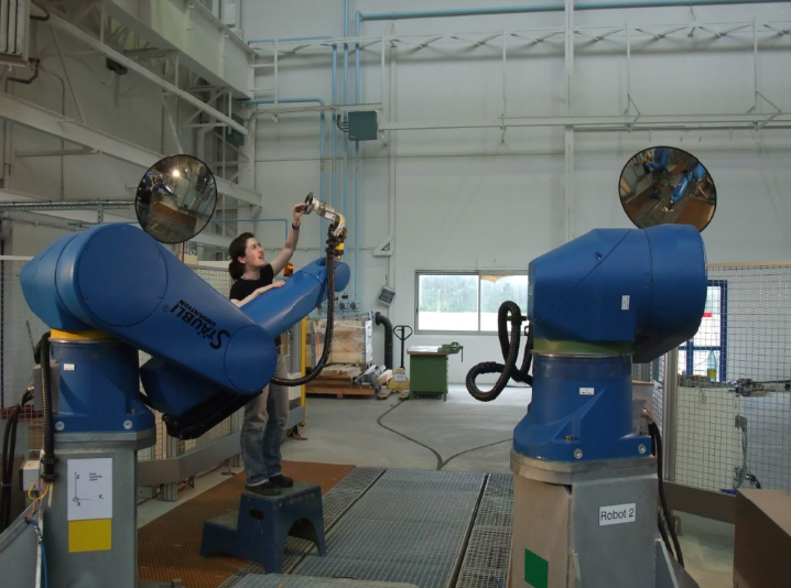
We also measure the spatial grid by moving to dozens of nominal points with the tooltip and various axes of the robot. Using the deviations between the actual and nominal data, an experienced operator can then reteach the robot.
Furthermore, laser trackers can be used to record the actual tracks of dynamically driven paths (3D point acquisition can then take place at up to 1,000 Hz). 6DOF equipment can be used to determine additional information such as DH parameters as well as tilts and twists of the tooltip.
Positioning and staking out
For production and assembly cycles to run smoothly and, in some cases, fully automatically, all machines and systems involved must be precisely aligned and positioned in relation to each other.
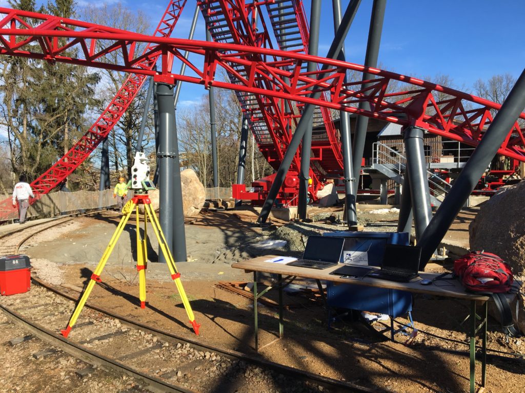
For the basic alignment of machines and equipment in production halls, classic standard geodetic tasks are used:
- Staking out of hall layouts
- Positioning in 2D and 3D systems
- Alignments
- Level alignments
- Parallelisms
- Perpendicularities
In addition to large-volume alignments, the methods can also be carried out for small-volume objects:
- Alignment of several rollers to each other
- Positioning of small components such as brackets on larger carriers
Dynamic measurement
Acquiring measurement data with static single points does not apply to all applications. If factors such as time, data volume or movement play a role in the measurement, dynamic methods can be used.
This applies to robots, but also:
- Real-time deformation measurements
- Tracking of motion sequences
- Monitoring of assembly processes
Successive measuring points can be recorded in two different ways during dynamic measurements:
- Using a spatial distance interval (for example, with a 1/10mm or more distance between each point)
- Using a temporal distance interval (from a fraction of a second to hours or even days)
Nominal-actual comparison
Today, design data are generally available in the form of CAD models, which build the basis for many component inspections. In terms of metrology, VMT can check the following issues:
- Does the component fulfil the specifications from the design?
- Are there any deformations or production errors?
- Are serial parts produced with consistent quality?
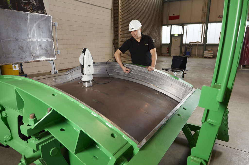
The measurement instrument is first positioned in relation to the part in the same coordinate system. Various alignment methods and transformations are used to aligning the measurement object. These include Best-Fits via defined reference points, geometries or via user-defined object points.
Afterwards, measurement data on the geometries and surfaces to be inspected is statically or dynamically recorded. The comparison of the actual data with the nominal data of the CAD model is graphically shown with false-colour visualisation. The quality assessment is facilitated by the display of measured values in tabular form. Simultaneously, tolerance specifications and other GD&T specifications can be checked and logged.
Geometric Dimensioning and Tolerancing (GD&T)
When assembling several components and checking dimensional accuracy, it is important to adhere to manufacturing tolerances from the design. They are intended to ensure functionality and minimise the risk of component failure during its service life.
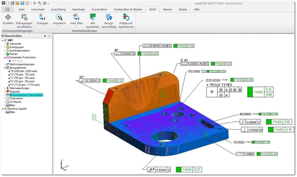
Examples:
- Concentricity of a shaft
- Parallelism of rollers
- Flatness and squareness of stamping machines
Inspections often start with the smallest components and continue through the entire production and assembly cycle of machines and plants.
Tests can be performed against constructed nominal data that have different origins:
- Data from 2D drawing files
- Data in 3D design files from CAD programs
Scanning
In industrial measurement, scanning is used for a wide variety of measurement tasks. The area-based acquisition of measurement data on surfaces creates point clouds for nominal versus actual comparisons, geometry checks, initial sampling, quality controls and inspections.
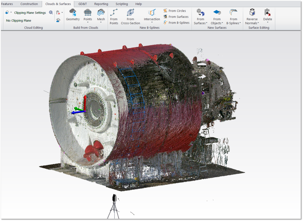
Digitisation and reverse engineering are used for dimensioning, CAD data creation, polygon mesh generation and data capture for 3D printers, as a basis for milling positive and negative moulds, or simply to create digital models for archival purposes.
Test report generation
Periodical geometry checks of machines and plants, for example once per year, are an important contribution to quality assurance. Create clear inspection reports for this purpose, which can be used for documentation and as verification for end customers.


